Easy TX Inhibit Circuit for K3
Learn from my mistakes 🙂
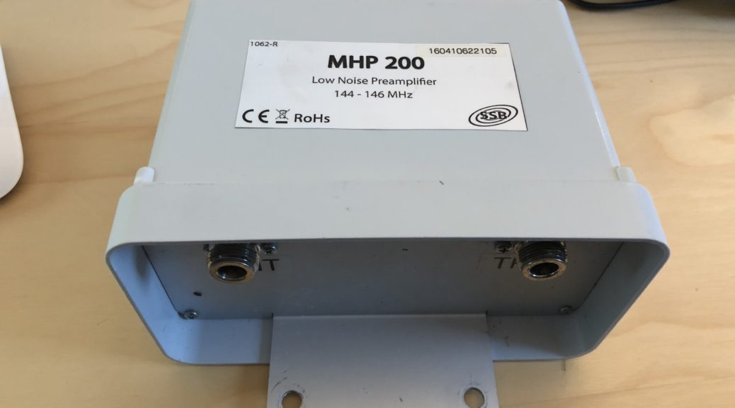
I blew up two SSB electronics MHP-200 preamps while building and testing my current portable EME station. I hope this article helps someone else not go down that path.
When I first started out with the K3 and EME I was using the TimeWave Navigator external sound card.
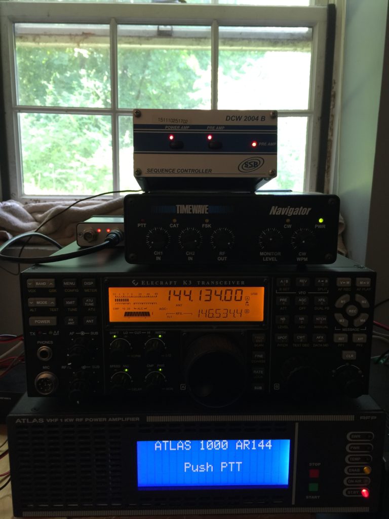
This worked fine and I was successful in making the appropriate cables to go from the K3, Navigator and the SSB Electronics DCW2004B sequencer. WSJT would enable PTT via the Navigator, the Navigator’s PTT line I would feed into the sequencer for PTT IN, then as designed the LNA would first be switched out, then the Amplifier PTT would be keyed and finally the K3 would send RF through the chain. The process would reverse itself when the TX sequence was over.
This worked perfectly until you don’t use the navigator sound card to PTT. oops. The first time this happened was while I was in J8 and I was working local tropo on 2M. I grabbed the hand mic, PTT and talk. BOOM, bye bye preamp. The Mic PTT was not in the sequencer circuit so 800w went directly into the preamp. Sent the LNA in and had it repaired. This happened a 2nd time while I was testing the station for full remote operation. Again, forgetting the LNA was inline, the K3 was keyed remotely by VOX and once again, BOOM, bye bye preamp.
Well, I started getting tired of this process of smoking expensive LNA’s so I went looking for a better solution.
I have since sent the K3 back into Elecraft to have some updates done and one of them was the bring it up to a K3s along with the built in sound card and USB connector. This is great, this consolidates 3 wires (Serial + 2 Audio cables) down to 1 USB cable. This also allows me to eliminate the entire external sound card system! bye bye navigator.
Now the issue arrises on how do you “interrupt” a direct PTT connection coming from the K3 itself to leverage the input PTT on the sequencer?
K3 CONIF Menu Item:
TX INHIBIT = HIGH
That’s how 🙂 Along with a very simple circuit and absolute magic happens.
The simple circuit.
I first found this great article from Ed KL7UW’s site.
Here is Ed’s multi band circuit if you have a bunch of VHF transverters hung off your K3.
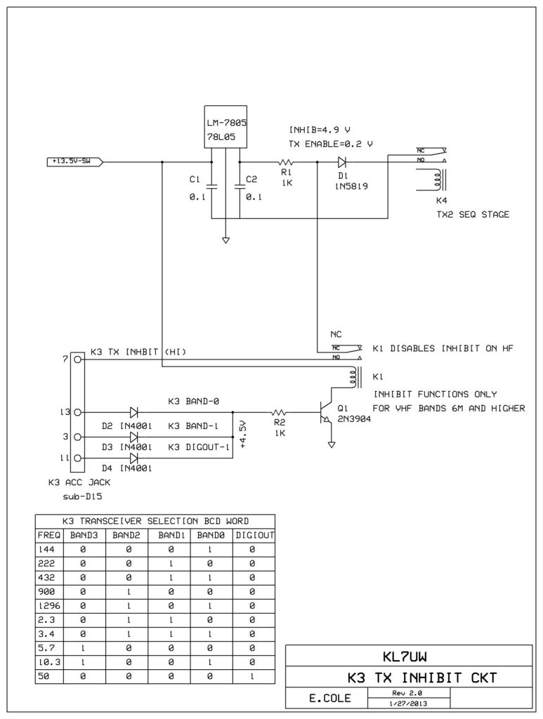
This is great if you have a bunch of bands, what if you only needed one band like me, 2m? So I emailed Ed and he shot right back with this email.
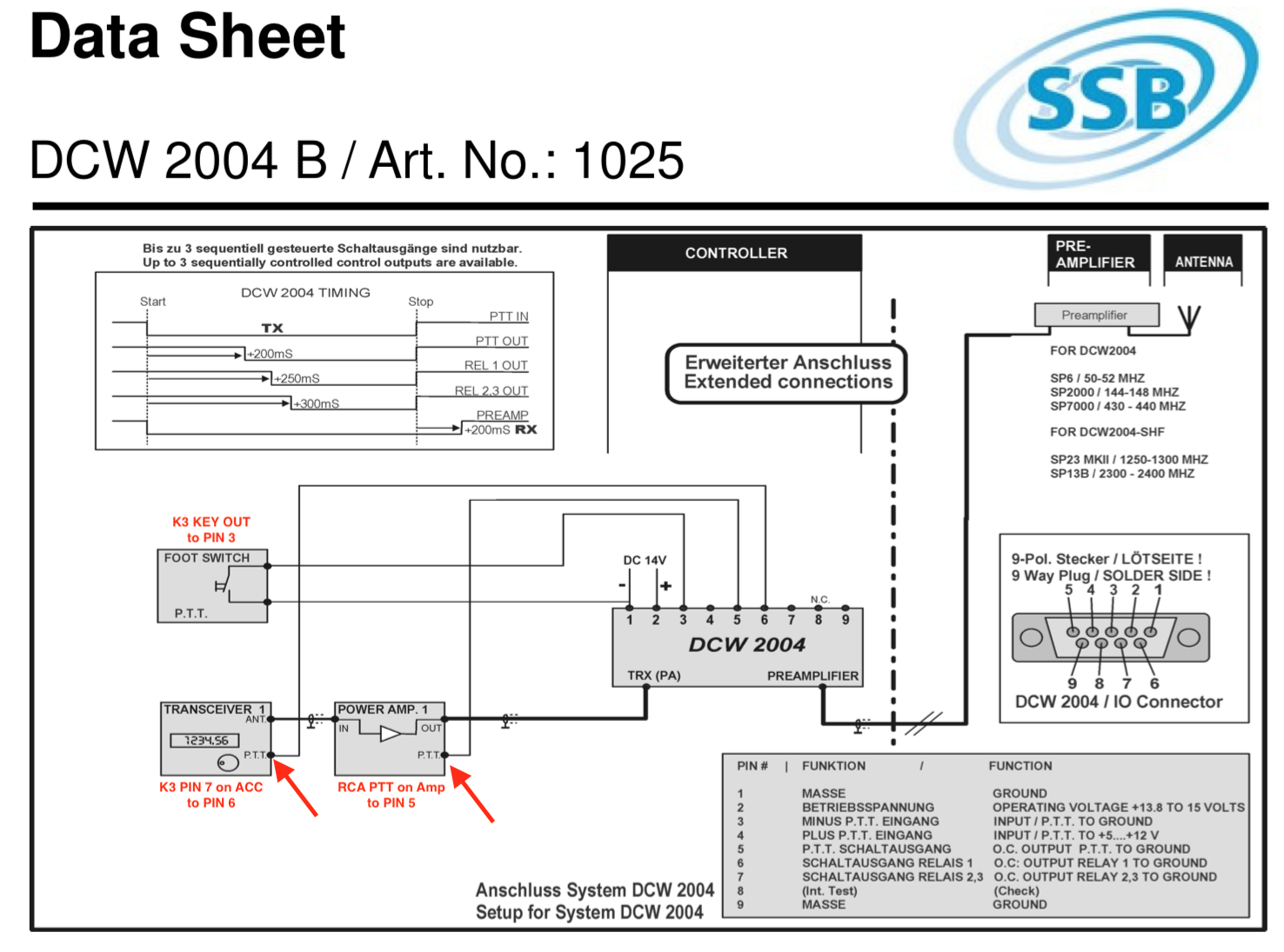
If you only run 2m the diodes D2, D3, and D4 plus Q1 and K1 are not needed. Just run from R1 to pin-7 on the accessory jack. A simpler ckt uses a 5K resistor from +12v at the 12vdc OUT jack (RCA-phono female jack next to the power-pole jack to pin-7 (resistor drops 12v down to 5v). Grounding pin-7 side of the resistor will enable Tx if INHIB = ON in the menu. Last stage of your sequencer should supply this ground in Tx.
Now we are cooking with gas!
I asked WW1X to look over the game plan with me to make sure that I had all the right connections going to the right places between the K3 and the sequencer.
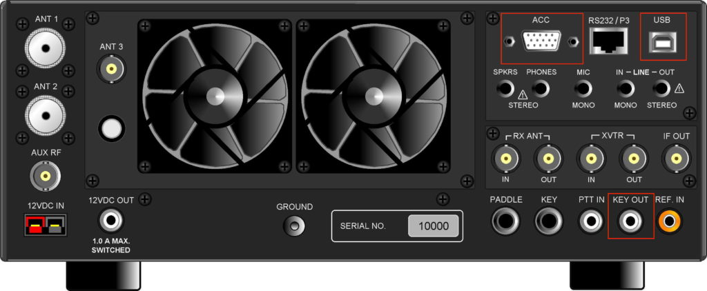
On the K3 we are dealing with a total of 3 connectors. (Optionally 4, more on this later)
- Key OUT (RCA)
- ACC (DB15)
- USB
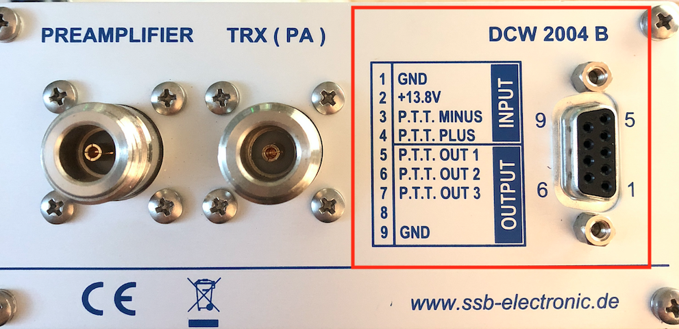
On the DCW20004B we only deal with the DB9 connector.
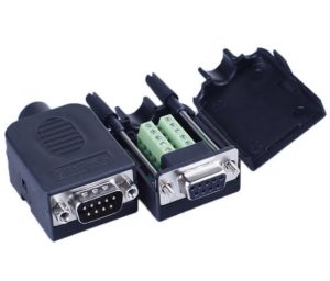
Soldering the DB9/DB15 pins can be a major PITA, I decided to order these from amazon and use these instead.

Here is the wiring schematic shown in the DCW2004B’s manual. This is what I used.
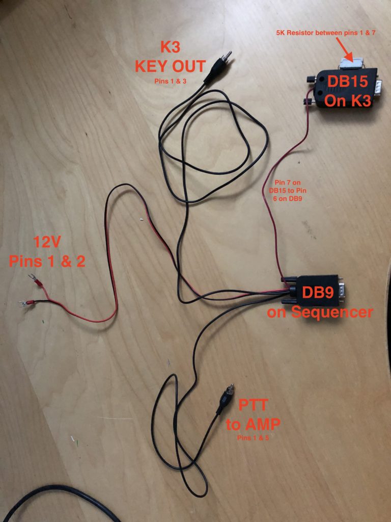
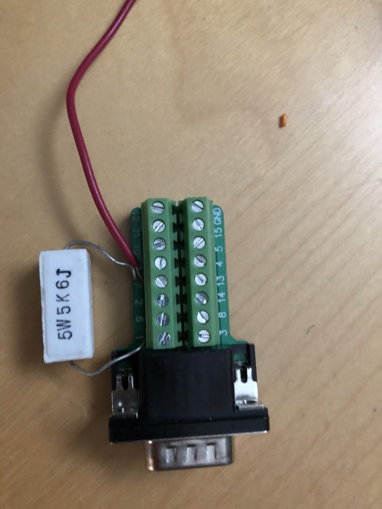
Here is the DB9.
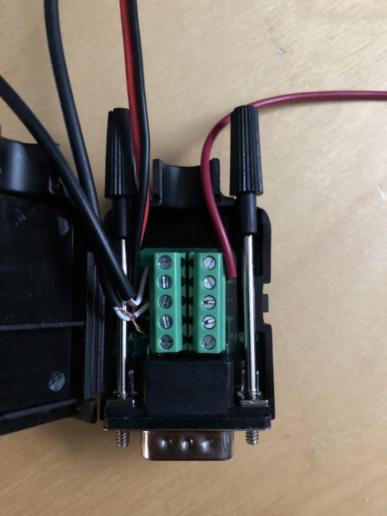
And the DB15. You need to place a 5K resistor between PIN 1 and PIN 7. (I know its a big resistor, all I had)
Thanks to WW1X for figuring out that we could use PIN 1 for +5V instead of the K3’s +12v RCA output!
There you have it! The beauty of this solution is no matter how you key the K3 ( Direct PTT, local Microphone, CW paddle, etc) you will never smoke out the LNA! Be sure make sure you have the TX INHIBIT = HIGH turned on in the K3’s CONFIG menu.
When you enable the TX INHIBIT you should see the K3’s main display show the “TX” badge “Flashing” like when you place the K3 into “TEST” mode. This is how you will know the INHIBIT feature is working.
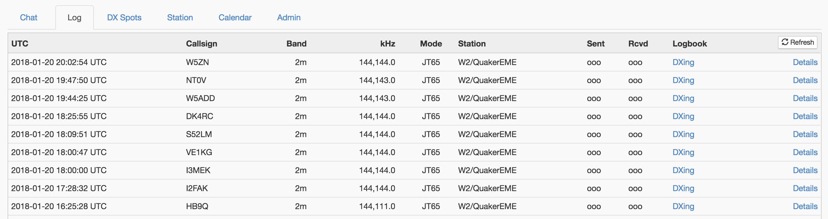
Here are my first 10 100% remote contacts after getting the new circuit up and running.
Thanks to WW1X and KL7UW for their much appreciated skilz on this project. If you have any comments, questions or improvements please leave them in the comments section below.